Thursday, September 23, 2010

Activity 12: Color Image Processing

Have you ever tried fiddling with the settings on your camera? One specific setting that is common to most cameras is the white balance setting. White balance settings lets the user change the white balancing constants suitable for the capturing conditions.

Looking at it in a scientific perspective, image captured by color cameras are defined by the integral product of the spectral power distribution of the incident light source, the surface reflectance of the object, and spectral sensitivity of the camera used.

R,G, and B are the red, green and blue values of a pixel in the image. The K in the equations above are balancing constants.

To further observe what is white balancing, let's take images for different white balance settings in a specific lighting condition.

Figure 1. Images taken under fluorescent lighting in different white balance settings (clockwise from top left: automatic, daylight, tungsten, and fluorescent).

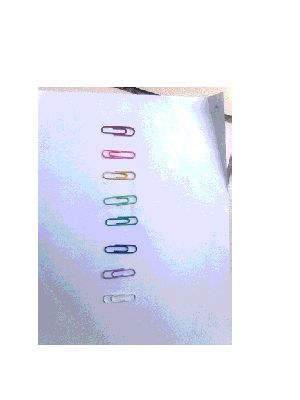
Figure 2. Images taken under natural ambient lighting in different white balance settings (clockwise from top left: automatic, daylight, tungsten, and fluorescent).

Figure 3. Images taken under direct sunlight in different white balance settings (clockwise from top left: automatic, daylight, tungsten, and fluorescent).

We can see that by changing the white balance setting of the camera, the color of the images produced are different from that of the real object. However, we can see that with the automatic white balance setting, it is able to correct the colors of the images produced for any lighting condition.

In this activity, we will simulate how this automation works. There are two of algorithm for automation, the white patch algorithm and the gray world algorithm. The white patch algorithm uses the color layer values of a pixel of a white object in the image for normalization in each color layer, while the gray world algorithm uses the average of each color layer for normalization in color layer.

Figure 4. White patch algorithm results of images taken under room lighting condition in daylight, fluorescent and tungsten white balance.

Figure 5. Gray world algorithm results of images taken under room lighting condition in daylight, fluorescent and tungsten white balance.

Figure 6. White patch algorithm results of images taken under natural ambient lighting condition in daylight, fluorescent and tungsten white balance.

Figure 7. Gray world algorithm results of images taken under natural ambient lighting condition in daylight, fluorescent and tungsten white balance.

Figure 8. White patch algorithm results of images taken under direct sunlight condition in daylight, fluorescent and tungsten white balance.

Figure 9. Gray world algorithm results of images taken under direct sunlight condition in daylight, fluorescent and tungsten white balance.

We can see that after applying the two algorithms on unbalanced images, the colors are corrected. However, saturation occurred ob both images. The saturation was caused by high exposure value setting of the camera.

Now lets try to apply the two algorithms in an image that has one dominant hue.

Figure 10. An image that has red as a dominant hue and has one white object.

Applying the two algorithms to the image in Figure 10.

Figure 11. (left) White patch algorithm and (right) gray world algorithm applied to the image in Figure 10.

We can see that the resulting image of the white patch algorithm is almost the same as the original. On the other hand, the resulting image of the gray world algorithm has saturations. From this, we can say that white patch algorithm is better than the gray world algorithm.

In summary, we have discussed what is this white balance thing in our camera and how does it work. We also found that white patch algorithm is better than the gray world algorithm. I will give myself a grade of 10 for this activity. Even though doing this activity is very tedious, it is fun to play with! =D

Reference:
  • Dr. Soriano. Applied Physics 186 activity manual: A12-Color Image Processing. 2010.
  • May Ann Tenorio for the pictures!

Tuesday, September 21, 2010

Activity 14: Image Compression

Image compression is a neat way to save memory space in storage devices. In this activity, our goal to convert an image to a format that would take less memory space for storage. The method used in compressing the image is the same compression method used in JPEG images.

First we pick an image of our choice, and then convert it to a grayscale image.

Figure 1. A 400x400 pixels image that was used for this activity. This image was obtained from deviantart.com.

Figure 2. Grayscaled image that will undergo compression.

We then cut the image into blocks with 10x10 pixels, then we vectorize it. After vectorization, we then gather all the vectorized blocks into a single list.

Principal components analysis (PCA) was then applied to the vector list. We used the built-in function in scilab, pca. The built-in function, then returns a list of eigenvalues, eigenvectors (eigenimages) and coefficients. The eigenvalues are needed to determine up to what number of eigenimages are needed to reconstruct the image of the original image. The eigenimages and its corresponding coefficients are the ones that are used in image reconstruction.

After PCA was applied on the grayscaled image, the 10x10 pixels eigenimages are obtained by arranging and concatenating the block. The eigenimages are shown below.

Figure 3. Eigenimages obtained after applying PCA on the image.

These eigenimages are the ones that will be used, together with its corresponding coefficient per block, to reconstruct the whole image. The eigenvalues will determine how many eigenimages from Figure 3 are needed to reconstruct the image. The eigenvalues are plotted below;

Figure 4. Eigenvalues of the eigenimages.

Now let's proceed to image reconstruction using the eigenimages and their corresponding coefficients. Reconstruction using all the eigenimages will result to a lossless compression and no difference will be observe between the original image and the reconstructed image. So to observe difference, we threshold the eigenvalue sum to less than a hundred percent (99%, 90%, 80%).

Figure 5. Reconstructed image with 80% thresholding. Only the first 3 eigenimages are used for reconstruction.

Figure 5. Reconstructed image with 90% thresholding. Only the first 14 eigenimages are used for reconstruction.

Figure 5. Reconstructed image with 99% thresholding. Only the first 68 eigenimages are used for reconstruction.


We can see that as the thresholding in the eigenvalues increases, the quality of the image also increases. This is expected because as the number of eigenimages used increases, the more defined the reconstructed image will be.

Now let us compute the memory space needed for the uncompressed image and the compressed image. For the uncompressed image (grayscaled image), we have 400x400 pixels and each pixel has a single value that ranges from 0 to 1 with 256 intervals. So the total image memory used is 400 * 400 * 256= 40960000 bits. On the other hand, for the compressed image, we have 40x40 blocks and we have a maximum of 100 coefficients. So the total image memory used is 40 * 40 * 100 = 160000 bits. Wow! What a difference!

Now what if we used the computed eigenimages to reconstruct a different image. Let's say a flower shown in Figure 6.

Figure 6. Image used to see if reconstruction of this image is possible using eigenimages obtained from the image in Figure 2.

First, we need to cut this image again into 10x10 pixels blocks and then vectorize it. After vectorization, we need to get the coefficients of the eigenimages from the previous image by getting the dot product of each vectorized blocks with all of the eigenimages. After obtaining the coefficients, we can now do the reconstruction. We will do reconstruction using the first 1, 3, 14 and 68 eigenimages.

Figure 7. Reconstructed image using only the first eigenimage.

Figure 8. Reconstructed image using only the first 3 eigemimages.

Figure 9. Reconstructed image using only the first 14 eigemimages.

Figure 10. Reconstructed image using only the first 68 eigemimages.

Wow! The image was reconstructed even though the eigenvectors used are from a different image. Again, it is still evident that if the number of eigenimages used is increased the quality of the image also increase.

In this activity, it is very interesting to know that there is a convenient and optimal method that can compress large sized image memory to a significantly smaller image memory. And also, eigenimages of a specific image can be used to reconstruc other images. I deserve a grade of 10 on this activity for the frustrating indexing. =P

Reference:
  • Dr. Soriano. Applied Physics 186: A14 - Image Compression. 2010.

Tuesday, September 14, 2010

Activity 13: Color Image Segmentation

Segmentation in image processing is a process of partitioning digital images into a number of segments. So if we want to pick out a region of interest (ROI) from the digital image that has its own unique features, we can use segmentation. Segmentation can be done in colored images as well as gray scaled images. However, for gray scaled images, color information is lost and so selection rules in segmentation are limited. The goal in this activity is to pick out a ROI from a digital image that has its unique color information from the rest of the image. Also, since segmentation can separate a ROI by color differentiation, face recognition, which segmentation is often applied to, was tried.

Since we are using 3D images, a single chroma may have different shades. It is more convinent to differentiate colors if we transform our RGB (Red, Green, and Blue) image into an rgI (normalized Red, normalized Green, and brightness) image.
From the mathematical proof above, we can see that from RGB color space, we can use the red and green color probabilities, r and g, to express all the pure colors and have the quantity, I, to cover for the brightness.

Two methods are used in the segmentation process, the parametric method, which assumes that the probability of a certain pixel to a specific pure color is a Gaussian distribution, and the non-parametric method, which doesn't assume any probability distribution.

Parametric method
In this method, a subregion of the region of interest are obtained. The mean and the standard deviation of the red and green colors are calculated from the subregion.
The mean and standard deviation obtained was used as a parameter for the Gaussian distribution.
Where xi is the pixels of the normalized red or green layer of the image. After the probabilities of the red and green colors were calculated. The two was then multiplied to get the joint probability. The joint probability obtained show the segmented image.

Non-parametric method
In this method, a subregion of the ROI is also obtained. Then a 2D histogram (r-g) was then calculated from the subregion. Since non-parametric method does not assume any probability distribution, it directly relies on the histogram of the subregion of the ROI. Segmentation is done by back projecting the histogram obtained from the subregion. The back projecting method is similar to previous activity, Enhancement by Histogram Manipulation. The back projected image shows the segmented image.

Applying the Two Methods
We will use the image that we used in the previous activity, Image Types and Formats.
Figure 1. Image of a flower.
Suppose we want to segment the petals from the image. First we took a subregion from the petals.
Figure 2. Subregion of the ROI.

Now we apply the the parametric method.
Figure 3. Segmented image using parametric method.

Next, we apply the non-parametric method.
Figure 4. 2D histogram of the image in figure 1.

Figure 5. Segmented image using non-parametric method.

Comparing the 2D histogram in Figure 4 from the Normalized Chromaticity Space (NCS) in Figure 6, we can see that the two agrees with each other. The histogram has high values in the purplish region on the NCS.
Figure 6. Normalized Chromaticity Space.

Now comparing the results of the parametric and non-parametric methods, we can see that the parametric shows a smooth segmented image, while in the non-parametric method, a rough segmented image was acquired. The smoothness of the segmented image produced by the parametric method is due to the Gaussian probability spread. The spread included colors that are close to the color of the subregion used for mean and standard deviation calculations. On the other hand, the roughness of the segmented image produced by the non-parametric method was due to the discretization of the the values in the 2D histogram used for back projection.

From these results, it is clearly shown that segmentation by colors is possible. So how about we try to find different colored candies in this image.
Figure 7. Image of different colored candies. The image are taken here.

Now let's find all the blue colored candies using the parametric method.
Figure 8. Segmented image of all the blue colored candies.

Now let's try the green candies.
Figure 9. Segmented image of all the green colored candies.

Lastly, the red colored candies.
Figure 10. Segmented image of all the red colored candies.

Since segmentation is often used in face recognition, we'll attempt to do face recognition using segmentation by colors. The image we'll use is shown below:
Figure 11. My Toga picture.

We are using my face as the ROI, so we'll use a subregion from my face to compute the mean and standard deviation that will be used in the parametric method.
Figure 12. Subregion obtained from the ROI in the image in figure 11.

We now apply the parametric method.
Figure 13. Segmented image using parametric method.

Now let us try the non-parametric method.
Figure 14. 2D histogram of the subregion.

Figure 15. Segmented image using non-parametric method.

Image segmentation by color is successfully done, face recognition was also accomplished using two methods, the parametric and non-parametric methods. The images produced from the two methods differ in quality. The dissimilarities are accounted on how the two methods uniquely calculate color probabilities. I will give myself a grade of 10 in this activity since I have accomplished the objectives.

Reference:
  • Dr. Soriano. Applied Physics 186 activity manuals: A13-Color Image Segmentation. 2010.
  • http://www.ica-d.com/puzzle/play/memb/kids/candies/0candies4-d.html.